Home » Without Label » Ne555 Timer In Automatic Star Delta Starter : Star Delta Starter Y D Starter Power Control Wiring Diagram : Here you can see the control circuit diagram of automatic star delta starter.
Ne555 Timer In Automatic Star Delta Starter : Star Delta Starter Y D Starter Power Control Wiring Diagram : Here you can see the control circuit diagram of automatic star delta starter.
Ne555 Timer In Automatic Star Delta Starter : Star Delta Starter Y D Starter Power Control Wiring Diagram : Here you can see the control circuit diagram of automatic star delta starter.. This indicates that the supply voltage in star mode was 440 roots of 3 whereas in delta there was full voltage supply of. That is the time for change over from star to delta sequence.setting your timer with the time that we record and test run. Two timers one is on delay timer and another is off delay timer.on delay timer is used for making on the star and delta contactor.where as the off delay timer is used for holding the control circuit that means if power becomes off for some reason. Automatic star delta starter using relays and adjustable electronic timer for induction motor. As you see in the above star delta starter diagram, first, an nc push button switch is connected to stop the operation.
Direct online starter animation diagram. An arduino is used as a timer in this project automatic star delta starter using relay for three phase induction motor, where pin number 2 is used for start and pin number 3 for stop. Set the stop watch and measure the time from starting (0 rpm ) until it reach 80% of motor speed.example if full motor speed is 1400 rpm,so for 80% full speed is around 1,120 rpm.so stop the watch and take the time reading. Star delta starter wiring diagram, this post is about the main wiring connection of three phase motor with star delta starter and control wiring diagram of 1 mccb circuit breaker 3 magnetic contactors 3 phase motor thermal overload relay / electronic overload relay ocr an on daily timer (8 pin timer. The pin number 2 starts the timer with starting of motor in star connection and after 30 seconds the.
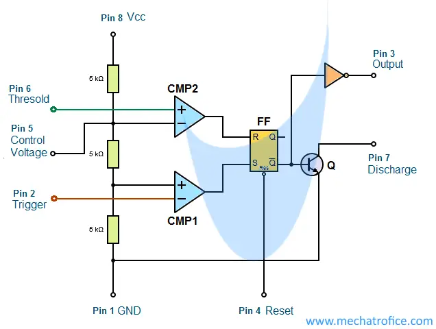
555 Multivibrator Circuits Tutorial Astable Monostable Bistable from mechatrofice.com Some of those are self starting, rugged construction, high efficiency, good power factor and ease of control, etc. The pin number 2 starts the timer with starting of motor in star connection and after 30 seconds the. Typical circuit diagram of star delta starter plc plc ladder plc so this time i want share my simple star delta circuit diagram completed with power and control line circuiti hope it can be as basic reference for. Star delta starter y starter capacity control wiring. • the 555 timer ic is an integrated circuit (chip). This indicates that the supply voltage in star mode was 440 roots of 3 whereas in delta there was full voltage supply of. Control circuit is present which consists of timer contacts. In star mode, the lamps would glow dim and in delta mode operated by timer it will glow with full intensity.
• the original name was the se555 (metal can)/ ne555 (plastic dip).
The on delay timer diagram is also shown in the diagram. Automatic star delta starter using relays and adjustable electronic timer for induction motor project synopsis due to the wide variety characteristics of the induction motor, it plays the premier role in the industrial sector. This drawing has two circuir. A 8 pin timer is used. In the control wiring diagram, all magnetic contactors coils are rated 220 vac. Automatic star delta starter using relays and adjustable electronic timer for induction motor abstract the project is designed to provide low voltage start to induction motors. As you see in the above star delta starter diagram, first, an nc push button switch is connected to stop the operation. Get latest price from the seller. Star delta starter control circuit diagram. In the above star delta starter control circuit wiring diagram with timer and normally close push button/normally open push button switch. Lamp dimmer using ne555 this project is about simple lamp dimmer project using ne555 timer ic. When the fault occurs the thermal overload relay will trip the circuit. Automatic star delta starter using relays and adjustable electronic timer for induction motor 555 timer:
This indicates that the supply voltage in star mode was 440 roots of 3 whereas in delta there was full voltage supply of. Star delta starter wiring diagram, this post is about the main wiring connection of three phase motor with star delta starter and control wiring diagram of 1 mccb circuit breaker 3 magnetic contactors 3 phase motor thermal overload relay / electronic overload relay ocr an on daily timer (8 pin timer. Some of those are self starting, rugged construction, high efficiency, good power factor and ease of control, etc. A 8 pin timer is used. Automatic star delta starter using relays and adjustable electronic timer for induction motor 555 timer:
18 Star Delta Ideas In 2021 from i.pinimg.com The pin number 2 starts the timer with starting of motor in star connection and after 30 seconds the. Star delta control wiring diagram with timer. When the fault occurs the thermal overload relay will trip the circuit. In this tutorial we will show the star delta y d 3 phase induction ac motor starting method by automatic star delta starter with timer with schematic power control and wiring diagram as well as how star delta starter works and their applications with advantages and disadvantages. • the 555 timer ic is an integrated circuit (chip). Get latest price from the seller. Dosto aaj ki is video me aap dekheenge star delta starter control circuit diagram or kaise kaam karta hai #stardeltastartercircuitsubscribe yk electrical for. The automatic star delta starter using relays and microcontroller as timer device is a standalone system that is capable of switching the motor from star to delta mode of operation to keeping the system functioning properly.
The on push button starts the circuit by initially energizing star contactor coil (km1) of star circuit and timer coil (kt) circuit.
As you see in the above star delta starter diagram, first, an nc push button switch is connected to stop the operation. We receive three single phase ac power supply through three 230/12 volts single phase step down transformers. Some of those are self starting, rugged construction, high efficiency, good power factor and ease of control, etc. The 555 timer ic is an integrated circuit (chip) implementing a variety of timer and. Control circuit is present which consists of timer contacts. In this tutorial we will show the star delta y d 3 phase induction ac motor starting method by automatic star delta starter with timer with schematic power control and wiring diagram as well as how star delta starter works and their applications with advantages and disadvantages. In the control wiring diagram, all magnetic contactors coils are rated 220 vac. Pin number 8 is used for star and 9 for delta connection. When the fault occurs the thermal overload relay will trip the circuit. Here you can see the control circuit diagram of automatic star delta starter. • the original name was the se555 (metal can)/ ne555 (plastic dip). The automatic star delta starter using relays and microcontroller as timer device is a standalone system that is capable of switching the motor from star to delta mode of operation to keeping the system functioning properly. • 20 transistors, two diodes, and 15 resistors on a silicon chip.
Automatic star delta starter using relays and adjustable electronic timer for induction motor. The pin number 2 starts the timer with starting of motor in star connection and after 30 seconds the. Two timers one is on delay timer and another is off delay timer.on delay timer is used for making on the star and delta contactor.where as the off delay timer is used for holding the control circuit that means if power becomes off for some reason. As you see in the above star delta starter diagram, first, an nc push button switch is connected to stop the operation. Next, the circuit goes through the nc terminals of the thermal over load relay.
Star Delta Starter Wiring Basic Knowledge With Timer Yk Electrical Youtube from i.ytimg.com Here, timers are changing the motor connection from star to delta. Lamp dimmer using ne555 this project is about simple lamp dimmer project using ne555 timer ic. Wiring diagram star delta schneider. Automatic star delta starter using relays and adjustable electronic timer for induction motor abstract the project is designed to provide low voltage start to induction motors. The contactors are smaller than the single contactor used in a direct on line starter as they are controlling winding currents only. Automatic star delta starter with timer for 3 phase ac motors in this tutorial we will enactment the star delta y 3 phase induction ac motor starting method by automatic star delta starter subsequently timer subsequent to schematic facility control and wiring diagram as competently as how star delta starter works and their applications in. The currents through the winding are 1/root 3 (58%) of the current in the line. We receive three single phase ac power supply through three 230/12 volts single phase step down transformers.
Star/delta starters are probably the most common reduced voltage starters in the 50hz industrial motor world.
Automatic star delta starter using relays and adjustable electronic timer for induction motor. Star delta starter y starter capacity control wiring. That is the time for change over from star to delta sequence.setting your timer with the time that we record and test run. A 8 pin timer is used. When the fault occurs the thermal overload relay will trip the circuit. Some of those are self starting, rugged construction, high efficiency, good power factor and ease of control, etc. In this tutorial we will show the star delta y d 3 phase induction ac motor starting method by automatic star delta starter with timer with schematic power control and wiring diagram as well as how star delta starter works and their applications with advantages and disadvantages. The contactors are smaller than the single contactor used in a direct on line starter as they are controlling winding currents only. Automatic star delta starter using relays and adjustable electronic timer for induction motor project synopsis due to the wide variety characteristics of the induction motor, it plays the premier role in the industrial sector. Star delta control wiring diagram with timer. • the original name was the se555 (metal can)/ ne555 (plastic dip). Next, the circuit goes through the nc terminals of the thermal over load relay. The automatic star delta starter using relays and microcontroller as timer device is a standalone system that is capable of switching the motor from star to delta mode of operation to keeping the system functioning properly.